| Home > Robots > Agrippa > December | |
| December | |
![[December]](ldec.gif)
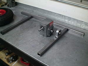 |
The lone speed reducer awaiting a frame to work within. Since all the trick power transmission is located in the rear segment of the Agrippa (more weight for counterbalancing) I started on that first. The large spans of steel in the frame are made from 1 inch square tube steel. It welds beautifully and is both cheap and light. I know how soft it is after working with its 0.5 square inch cousin on the arm of the Alexander, so I'm using it with pure abandon. A ball bearing pillow block supports the overhung load of the wheel off each side of the segment. |
 |
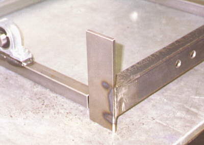
The first weld of the project, and it's a darling thanks to my new auto-darkening welding helmet. Instead of a smoked glass window that encourages misalignment at the start of the weld, the viewport of this $200 sucker is normally clear. But upon exposure to bright light (ie. the plasma arc) it auto-darkens in a mere 10ms. (I read once that this technology was developed for the canopy of the B1 bomber to protect the crew while vaporizing eastern Europe. Glad to have it added to my arsenal.) |
| 10. | Emergency entry vehicle for crack houses |
| 9. | Dangerous entertainment for childrens' parties |
| 8. | Viable substitution for noisy gas powered leaf blowers in LA |
| 7. | Float for the Rose Parade 1999 (please send flowers, seeds, etc.) |
| 6. | Blatent kiss-up when requesting sponsorship from Caterpillar |
| 5. | Remote Harley-Davidson yuppie rider suppression device |
| 4. | Great way for Hillary to keep up with Bill at the White House |
| 3. | El Niño evacuation device |
| 2. | Downhill slalom TreeGuard® (when properly outfitted with skis) |
| 1. | Replacement form for antenna ball at Jack In the Box |
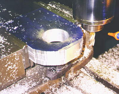 |
More aluminum! Here is a 1.25" thick block that will become half of the hinge that will join the front and rear segments. A precision hole down the middle will have Igus polymer bearings pressed into it. Here I've finished coarse milling the outside radius. Next I'll clean it up a bit with a 4 flute endmill and then use the belt sander to get the final radius. Its amazing how close to a circular path you can mill with a little practice. |
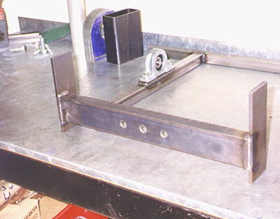 |
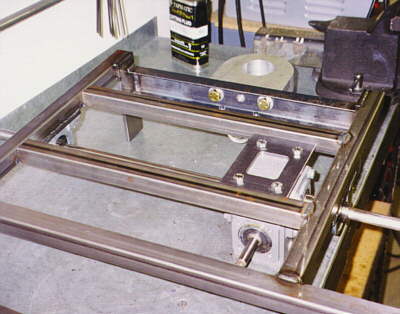
In the far background is the completed aluminum hinge part next to its steel counterpart that is layed out but not yet machined. Also you can see the 1/4" thick mounting plate benath the pillow block that holds the threads it mounts to. In front is the assembled coupling frame prior to welding to the main frame. Structural strength derives from the horizontal piece of U-channel steel. The three holes match to threads in the aluminum hinge part. |
 |
Most of the robot so far is made of AISI 1018 grade steel. This is a low carbon material, the "18" in its number indicating a 0.18% concentration. Being a bit on the soft side I've taken extra steps to keep the frame strong and prevent a few lone welds from taking all the forces. In fact during design I frequently draw force-body diagrams of the various parts to help me visialize their internal stress loads. |
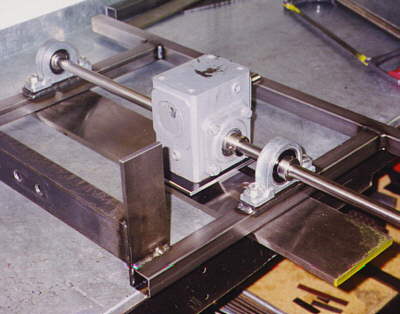 |
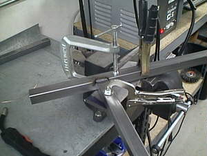
Here I'm playing with final alignment of the rear speed reducer. Its easier to see in other pictures that I've already machined a mounting plate for the bottom from hot rolled steel plate. Running down the center of the robot, parallel to the reducer's input shaft is the rear power take-off axle. A 1:1 sprocket drive couples the two and slots on that lower mounting plate allow the reducer to slide from side to side, adjusting the chain tension. That long piece of steel with the yellow end is a chunk of flat ground stock, perfect for aligning the parts square prior to welding. |
 |
Cross-rails have been added flush to the sides of the reducer mounting plate. Everything is flipped over here as I prepare to weld the mounting plate to the rails. In the background you can see a couple of grade 8 bolts holding the aluminum hinge part on to its mounting bracket. |
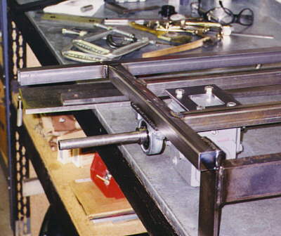 |
A few more shots of the above described scene. The 5/8" axle juts out where a drive wheel mounts. The wheel is overhung about 4" from the pillow block. This may be too much and in danger of bending but that depends on what material I use for the axle. Carlo Bertoccini, builder of Biohazard and future arena foe, has given me some great help in this area. (Only our robots are mortal enemies of each other. Most contestants stick together to help each other build the best robot they can.) | 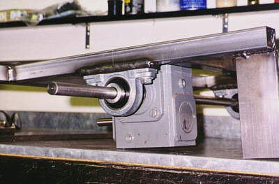 |