| Home > Robots > Agrippa > February | |
| February | |
![[February]](lfeb.gif)
|
The problem may have been that there was a Sonehenge monument on the stage that was in danger of being crushed. By a dwarf. |
 |
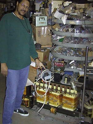
If you ever drive through Burbank, CA, you have to check out Apex Electronics. As you approach the open door, the smell of forty years of electronic surplus greets your nose. And once you enter, you know that four decades have passed; they've never even swept up! To the right, my friend Greg discovers a possible power transformer to use in the rail gun... |
 |
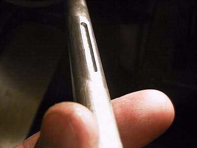 |
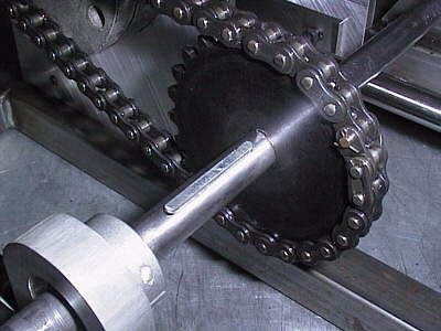
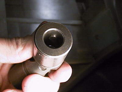
I've used keyways everywhere on the Agrippa. It's actually quite easy once you get the hang of it, and its about as "positive drive" as you can get. Here is the 0.50" dia. intermediate power transmission shaft keyed to receive a toothed sprocket. The keyway hole was easily machined with the mill. By making it oversized I permit variable alignment of the sprocket while retaining its positive connection. |
 |
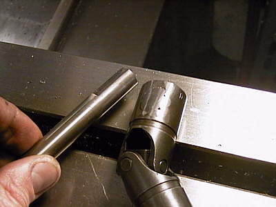 |
The intermediate shaft runs down the center of the robot coupling the two segments together through a U-joint. There was no way to broach the UJ without pressing the pins out of the "joint" part, so I had to come up with a non-set screw method of coupling it. After machining a flat in the end of the shaft to be coupled (left), I drilled a hole in the side of UJ collar. Then carefully clamping a dowel pin through the hole, pressed against the shaft, I welded the pin in place (right). Then I ground down the excess material to provide for clearance over center joint. The final product is a positive drive connection that is still adjustable - important for centering that UJ over the pivot center. |
 |
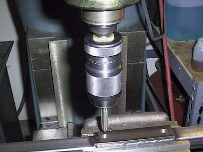 |
With everything coming together in the power-drive segment, it was time to fab the front segment that supports the bucket (or spike; they will be interchangeable). Here I am tapping the pillow block backplate holes on the mill. Since I've just drilled the hole without moving anything, the tap is perfectly aligned, not to mention square. By chucking up the tap, spinning up the mill, turning off the motor, and with one hand on the spindle brake, a controlled descent into the part is possible without tap breakage. Kids, don't try this in metal shop. | |
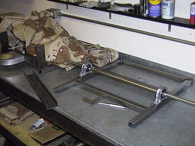 |
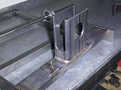
The front segment is coming together here, minus the central support bracket (the U channel). To the left, a genuine military pack cover keeps crud out of my smooth power transmission components. Getting ready to weld the steel half of the pivot bearing to the support bracket (right). |
 |
 |
After fussing and practicing the motion to make sure the feed wires don't bind anywhere, we have a beautiful weld. Subjecting custom parts to my homegrown welding skills stresses me out every time. | 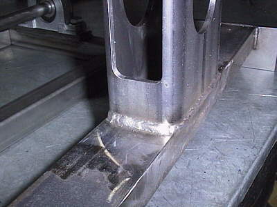 |
 |
I need servo feedback for the actuators that position the steering angle between the segments. In English this means that I want the bend angle to match the stick position on my RC transmitter. What I don't want is to have to manually realign the steering by using "a little more left" followed by "a little more right." This technique requires feedback from the steering mechanics. The idea is to have a small computer on board that controls the steering actuators. It decides which way to drive them by comparing the actual angle of the pivot joint to the commanded angle coming from the RC receiver. Essentially it amplifies the difference. | |
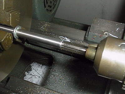 |
A linear potentiometer was available on the actuators for an additional $125. So I decided to make my own and show you how I did it. To start with, I joined an aluminum and steel rod of equal diameter by cutting some threads on each so that they would screw together. Aluminum is not paramagnetic, but steel is. That is a key fact here. |
 |
 |
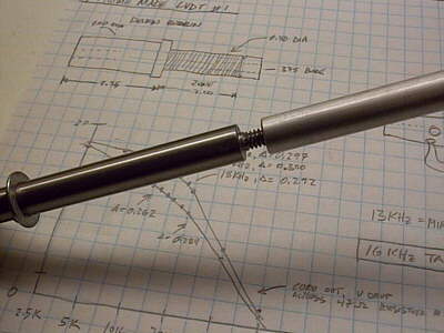
Now what I built is an inductive linear position sensor. It works by attenuating (decreasing the signal strength) of a sine wave that pumps a coil surrounding the Al-Fe rod. The more steel that is present inside the coil, or solenoid, the more energy is dissipated in the metal, effectively increasing the AC resistance of the coil. | |
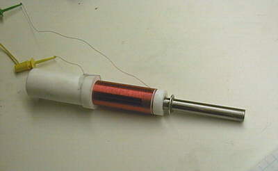 |
By rectifying the outgoing signal with some clever op-amp circuitry, I can see a zero to 5 volt DC signal that changes linearly with the position of the Al-Fe rod in the core. This position sensor, when bolted across the support brackets, will generate a feedback voltage proportional to the angle of pivot. With my function generator I was able to measure the resonant frequency of the coil at 16KHz, the place where I can achive the greatest dynamic range. (And yes, I hand wound that coil. Some red glypt varnish keeps it from spontaneously unspooling.) | |
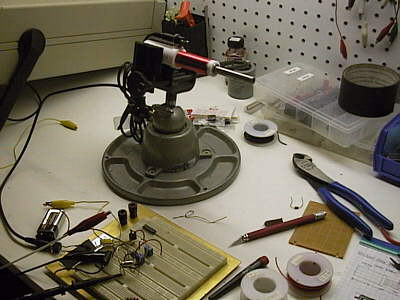 |
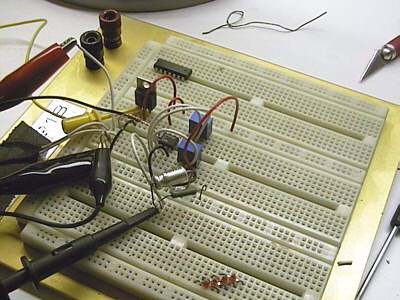
Here is the completed unit as I dial in the gain and offset values for the decoding circuitry (left). On the right, the breadboard electronics that make sense of the AC signal. Not shown: the PIC microcontroller with A/D input that will comprise the "brain" of this simple servo circuit (next month!) |
 |
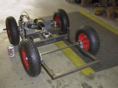 |
The first assembly of the two segments. Note the Coke can for scale. | |
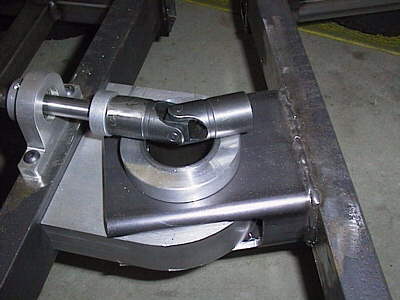 |
Zoom of the U-joint positioned above the central pivot. Shaft collars on both shafts (you only see one here) are used to position its center over the pivot axis. | |
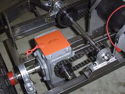 |
As promised last month, some information on the flat thermofoil heaters from Minco. Coated on one side with pressure sensitive adhesive, they will just stick right on top of the worm gear case. I chose models that produce 80W of heat when run on 120VAC wall current, significantly reducing the viscosity of the oil in the cases. This improves efficiency in power transmission for the 5 precious minutes of each battle. | 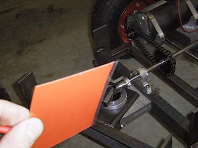 |