| Home > Robots > Agrippa > October | |
| October | |
![[October]](loct.gif)
What I'm going to cover this month is really the on-and-off work I've done since April. A lot of it was done in the weeks prior to BotBash'98 in Phoenix back in September - nothing better than showing up to a robot fight with a working robot!
Anyway, apologies or not, thanks for your continued interest and I hope you enjoy the following.
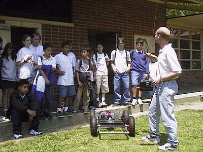 |
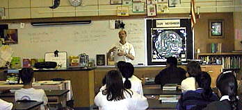
One of the things I'm real hip on is siezing any opportunity to talk about the science of building robots, especially to students. Sure I could keep building these machines with the implicit message "look at how cool I am," but that would be totally lame. Instead I'll keep building these machines with the explicit message "look how cool science is." Here I am speaking at a junior high career day. Even a vaguely operational version of the Agrippa was a hit. When I asked one class to name some fields of study that had to do with robotics, one girl answered "biology." Now that is potential. |
 |
 |
Back in the shop, here I'm eliminating the 12 volt gel cell that separately powers all the onboard electronics. This is a surplus DC-DC converter that will run from my main drive batteries while still providing me ground isolation and therefore noise immunity. Plus I save nearly a pound in weight. | |
 |
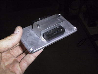
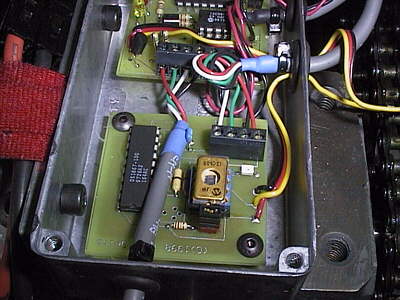
Two of the R/C interface boards I sell up in the Electronics section of the website are housed in this cast aluminum box for RF rejection. One, the RCE100, runs the monster 4QD power controller while the RCE300 generates an analog voltage reference command to the steering servo amplifier. I designed both boards for this robot but then discovered that other builders might find them useful in their projects, so I started selling them. The box is shock mounted above the rear speed reducer. |
 |
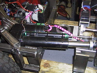 |
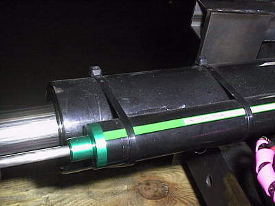
Possibly the coolest accomplishment since the April update was the completion of the steering system. This is a six inch 250lb. actuator that does the job. It takes a bit of practice to drive safely. So of course I learned this on the fly as I rocketed the robot down the foyer of the fancy hotel the BotBash'98 event was held at. Sure people stared and mothers hid their children. But hey, welcome to the Age of Robots. | |
 |
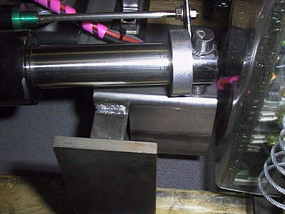
To the left, the rear end of the actuator is mounted to a diagonal spar on the front segment. It was tricky as the unit sweeps out a large area between full retract and extend. But with the usual amount of fiddling around I made it fit. To the right, the nose pivots on a rigid pin welded directly to the support frame. Overall it's quite solid. On the right you can also see a shaft collar that presents a mounting ear for the 6 inch linear pot that provides position feedback to the servo amplifier. The pot shaft is mounted through a rubber grommet to prevent temporary angular misalignmets from breaking the glide bushings. |
 |
 |
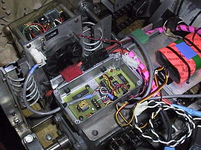
In earlier status reports I wrote of the custom inductive linear position sensor that was going to be used here. Well I ran out of time (and energy) so I forked over the $150 for a Midori Precision linear pot instead. It works as a voltage divider, feeding the voltage-encoded-position back to the Copley Controls model 413 servo amp on the right (that black box with the wires.) The servo amp works by moving the acuator in or out to zero the difference between the feedback voltage and the reference voltage coming from my R/C receiver. The blue screw pots on the top let me alter the gain of the loop, the zero offset and the integration frequency. It's totally dialed in. | 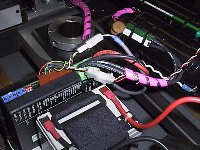 |
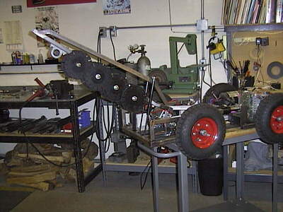 |
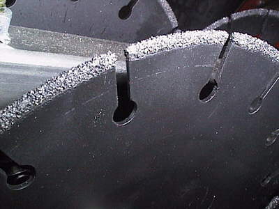
I take it back. An even cooler accomplishment was the construction of the Linear Blade Weapon, my alternative to the simple scoop the Agrippa was originally supposed to sport. In the weeks prior to Robotica'98 I awoke at 2AM with the idea for this weapon. Chain saws seem like really great weapons but in practice they fail miserably as the chain always jumps the track. So in the same line of thinking that makes the edge of a circle look straight if you look at a small enough piece, these overlapped blades spinning in the same direction approximate a linear cutting edge. | |
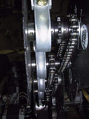 |
A thick walled length of square tube steel forms the backbone of the weapon to which the pillow block bearings mount. Sprockets connect #35 chain between the drive axles which are positively keyed. To the left you can see the LBW in it upraised position. To the right is a close shot of the blade edge - yes, that is carbide grit. I couldn't find this diameter blade anywhere on the west coast so it was through a generous company in Chicago that I obtained them in two days. The thought the idea of fighting robots was totally cool! |
 |
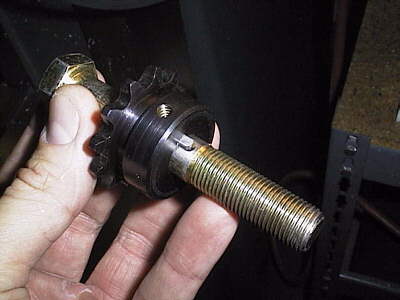 |
Since this weapon idea only came into existance a few weeks prior to it's delivery deadline, I made a few sacrifices to get it done quickly. The axles of the blades are grade 8 hex bolts that I milled keyways into. The whole assembly fits together like a big sandwich with blades on the extremes and then I really torque a castle nut on to smash it all together. A cotter pin keeps the nut from unscrewing. | 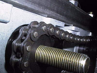 |
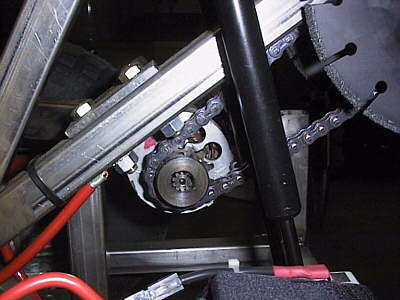 |
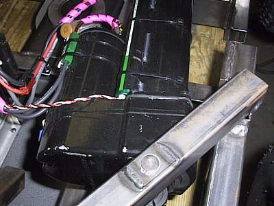
Power for the weapon comes from a dedicated 12 volt starter motor off a Honda V-twin motorcycle. It screams at 1kW start-up and 6,000 RPM. As a series wound motor it would theoretically self-destruct if run unloaded. A 2:1 reduction from the motor to the first blade axle gets the torque up and the blade RPMs down to a reasonable range. As it is the blades 'sing' when up to speed. Very scary. | 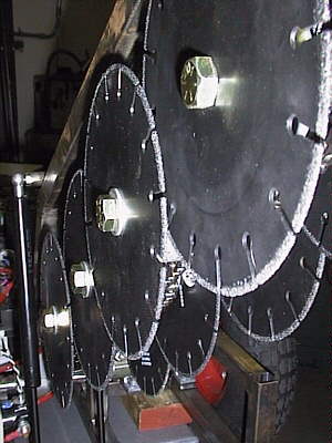 |
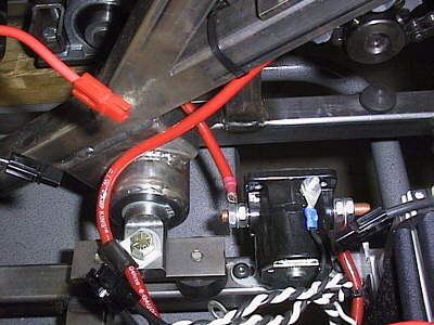 |
Check out the black solenoid contactor that is used to switch the weapon on and off. It's of a Ford pick-up truck. Power comes from three Yuasa NPH series gel cells in parallel. NPH is the high-rate discharge version. Together they can put 200 amps through that #8 wire into the starter. One of my RCE200 E-switches is used to control the solenoid. Also you can see the 1" dia. shaft that provides the swing bearing for the chopping action of the weapon. On each side two black rubber shock mounts isolate its destructive potential from the front frame. | |
 |
The LBW in the down position. I left the end of the spine tube open (just off frame) to accept a steel ramming point as it should make a great lance as a secondary attack mode. Gas charged shocks on each side of the weapon help counterbalance the large overhung load. The chopping action will be pneumatically actuated from the rear. I still have a lot of pneumatic gear from previous robots as well as a cool cylinder that '97 teammate Dave gave me. | |
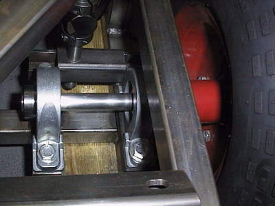 |
The great weight of this weapon forced me to mount it further back in the front segment than I had wanted. Unfortunately this prevented me from mounting the second speed reducer up front as intended for 4 wheel drive. Double pillow blocks now support the front wheel idle shafts. | |
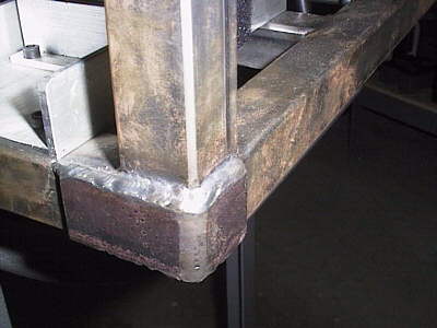 |
L-shaped sections of steel strap are welded on to all the corners to increase strength. | |
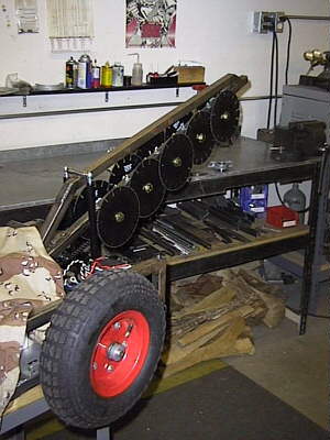 |
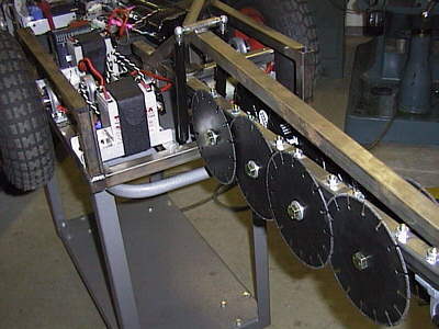
A final scaled picture of the LBW against the front of the robot. The terminal blade is removable to fit an interchangable steel fang as a possible anti-Blendo weapon. And at nearly four feet in length this weapon should really make an impact at the next event. Especially if I can get away with smaller drive system batteries and drop to the middleweight class. | |