| Home > Robots > Alexander > Late February | |
| Late February | |
![[Late February]](or-lfeb.gif)
Unfortunately, a change of this magnitude meant I had to start over on the frame. Bad.
But, around this time, a video arrived from my friend Andrew Lindsey. It had been shot by Daniel Russett at the '96 event and showed the Ag's battles. Perhaps the most embarassing scene was when the Ag went up against a wooden pyramid called Scrappy. After knocking it senseless, I remember thinking "Heck, I should just start ramming it - maybe something will break free." I hit it so hard that I ran up the side, lifting all 6 of my drive wheels off the ground. I was stuck. And I felt stupid. And I realized that I had made the same mistake with the frame design I had just abandoned for the Ax. So starting over gave me a chance to avoid this. Good.
I think you'll like the look of the new frame, too. I sure do.
(The old frame hangs on the wall of my den; the obsolete pillow blocks are on my monitor here at work; send me $5 and I'll send you one.)
 |
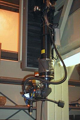
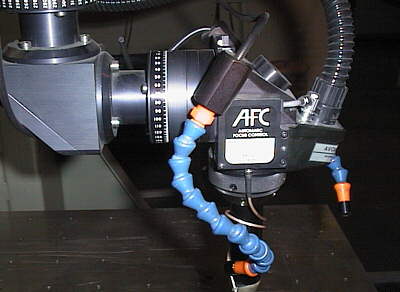
My cobalt motor arrived from Astroflight. It is what powers the cutting head at the end of the 3dof arm, generating over 1HP. This is the aluminum clamp I made to hold the motor in place. I pulled some info off the web on how to "Anodize in the comfort of my living room" so I'll probably try the scheme on this part if I have free time. |
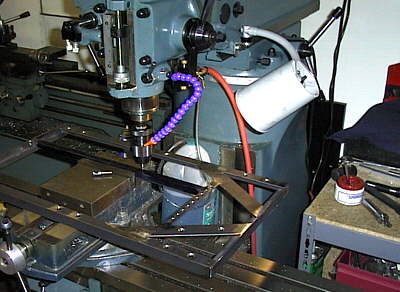 |
Here's the old frame clamped on my mill while I drill some holes to mount the bearing blocks. I tried to make some small adjustments to it in order to make it work, but no go. |
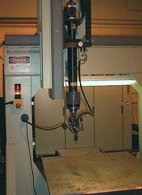 |
Meet Mr. Laser. Housed in the "laser room" at the Advanced Technology Corp. in Pasadena, CA, it burned the lightening holes in my rotary cutter. An Nd:YAG type, it generates 600W of laser energy that can be concentrated into a beam 0.014" in diameter. The laser itself is a dual flashlamp pumped rod, mounted horizontally behind the supports at top. The beam is deflected downward to the part, which rides on an actuated XY positioning table. |
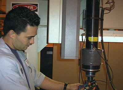 |
Meet Ed, the laser operator. A cool guy that takes pride in his work. "Man that steel was hard!" was the first thing he said when I came to pick up the finished part. We had it on the lowest setting, one inch/minute travel. "We've cut thicker steel, but never that difficult." As I related this to Mark Setrakian, Robot Wars legend and creator of the Master, he replied with "It figures that their toughest job would be for Robot Wars." 'Nuff said. |
 |
Here's a closer shot of the deflection head. The beam exits downward through the aperature that looks like the sharp end of a pencil. Various piping connections to the rest of the plant supply shielding gas that floods the cut area to prevent material reactions with the surrounding air. These pictures look really weird because the room lighting was this eerie orange color; sorta space age. I liked it. |
 |
Last shot of the head. ATC engineered this add-on swivel accessory for a job they were doing in-house, and ended up selling the design to the laser manufacturer. They're real players up there at ATC - lasers, electron-beam welders, etc. Did I mention that this Nd:YAG setup cost ATC a couple hundred thousand dollars? My job was only $140. |
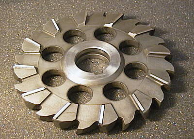 |
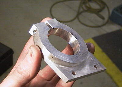
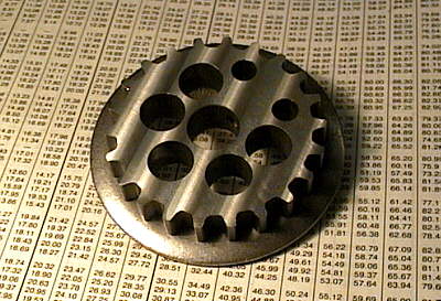
Well, here's the finished product. The eight holes reduced the weight by half of a pound. Significant. Should be really scary when installed on the arm in March. Then again, it was scary when Setrakian picked it up and slid four fingers into the holes while mumbling something about "steel knuckles"... |
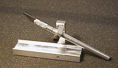 |
This is a cutting jig I made to slit the drive belts. The belt moves through the channel in the bottom while the blade is applied. Those belts I displayed last month are serious overkill, so half-wide versions, even derated, are still more than enough. |
 |
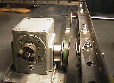
In the new belt drive scheme, I get away with using two drive pulleys per 3 axles. One complete unit on the middle wheel and a half on both the forward and rear axles. This is a half-pulley. The numerical tables in the background are the lifeblood of this drivetrain design; they specify the safe belt tensions at various RPMs. There's a world of difference between finding parts and finding the correct parts. |
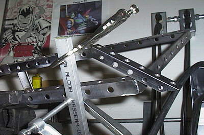 |
Here is the new frame being welded together. The frame in this picture is the pieces of angle that have lightening holes drilled in them. So far, I've drilled over 140 holes with a net savings of just about 1 pound. Why bother you ask? Try to crowbar 160 lbs. of heavyweight weapons and technology into a 100 lb. middleweight robot and you'll understand. And besides, I always liked the way the skeleton of the Hindenburg looked. |
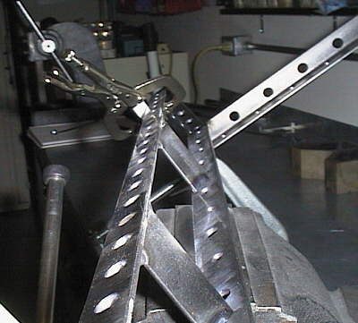 |
A long shot down the side (interior) while welding and grinding progresses. The steel angle I use it hot rolled, so before it gets embedded in the frame I take a flap disc sander to it. Removing all the forging scale not only makes it look nice, but makes scribing the layout die possible. |
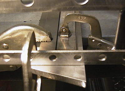 |
Getting everything rigidly aligned prior to welding usually takes all of the clamps in my toolbox. And getting it set in place requires 5 hands and an extensible eye. I use a MIG welder to join metal in my shop. If you're not familiar with one, it's like a continuous arc welder except that the weld wire is motor-fed through the welding head while enveloped in CO2Ar shielding gas. With enough patience, you could create a continuous seam weld 10 meters long. Dials and buttons adjust the weld current, wire feed speed and gas flow. It's fun, too. |
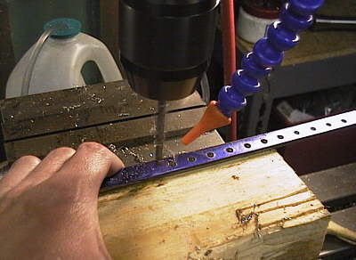 |
After you drill a few dozen holes of the same size, it becomes a game. Can I get the hot drill cutting to spin out of the drill bit and miss my hand? In general, no. |
 |
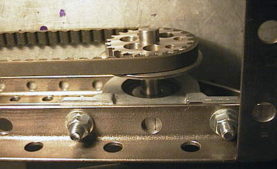
Here's the first mock-up of the belt drive scheme. The pulley flanges alternate on each axle to keep the belts from running into each other. There are some major advantages to this design:
|
 |
Continuing to mock up the frame with the power drive components. This shows the leading edge of the frame up front; the projecting axle will mount a wheel. The swept up design, taken from a WW2 German troop transport, is what will give the Ax an angle of attack/departure of 45 degrees. Specially designed bumpers will resist the vehicle's tendancy to bounce up on a target during collision. |
 |
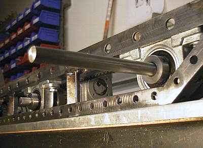
Here's a hip shot of the front drive pulley. The pillow blocks used for wheel bearings are on adjustable centers, so installing the belt is easy. Just pull and tighen when the correct tension is reached. |