| Home > Robots > HAZARD > February | |
| February | |

|
I'm going to place them in an easily escapable situation involving an overly elaborate and exotic death. |
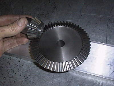 |
We ditched the 3L size V-belt weapon drive in favor of a bevel gear scheme. This had many significant ramifications: it was lighter, it moved the shock compliance from the drive to the blade and it got the drive motors horizontal. The last point was the most important as it directly lowered the blade edge, which we were very excited about. Step one was opening up the ring gear to fit our 1.50" chromoly driveshaft. |
 |
 |
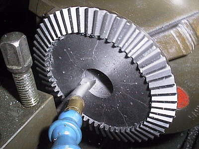
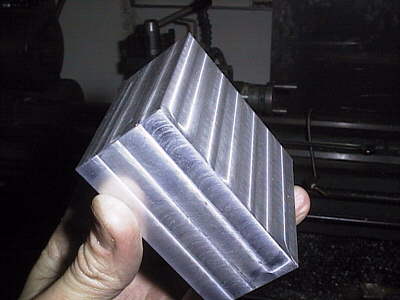
Ever tried to clamp on a bevel gear? I had to take some meat off the end to fit our motor shaft length so I built a quick jig out of aluminum. Clamping on the two C-shaped halves pressed on the gear hub and held it so I could mill some material off. | 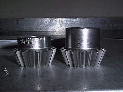 |
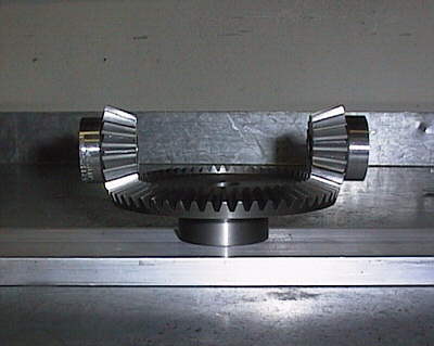 |
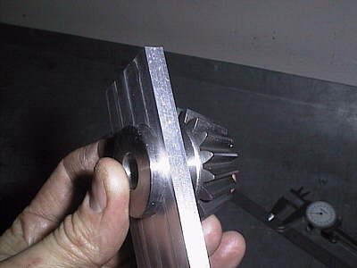
All the axle bores look square so this is a good start! The gears were stock from the Boston Gear catalog; I asked my friend Bob Pitzer to FAX over that section for me. The whole setup cost about $140. | |
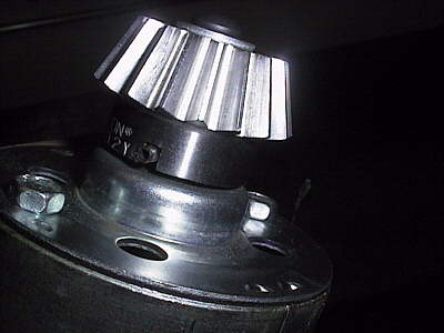 |
Here is the pinion installed on the motor shaft, retained by an existing roll pin at the bottom. I used the mill to lay a slot down the back of the hub to mate with the roll pin. Conveniently the end of the motor shaft had a 1/4-20 thread in it so a bolt held it all together. We always guessed this would be the prime failure point of the system and expected the roll-pin to shear. But it never did because of the slip clutch in our blade! |
 |
 |
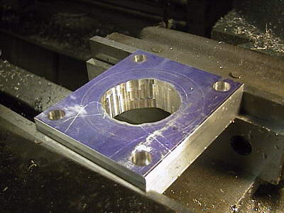
The weapon was built as a stand-alone module to aid in system test and to increase the stiffness of the robot in general. The spine of the weapon pod was a 20" chunk of 0.50" thick 6061 aluminum which I fly cut to reasonable flatness. The bottom bearing block was milled up first to hold the X-contact ABEC-5 ball cartridge. |
 |
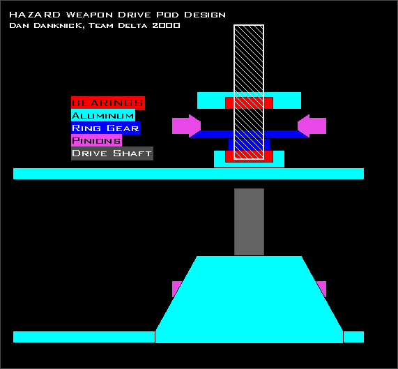 |
The basic design of the weapon pod was to float the drive axle between two massive ball bearings. The whole assembly would be constructed of thick 6061 and screwed tightly together; small and stiff! The symmetric and non-reversing torque of the drive motors would help with gear alignment. | |
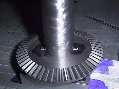 |
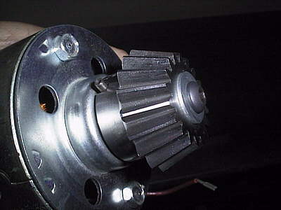
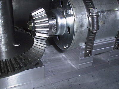
Attachement of the 4130 driveshaft to the cast iron gear was problematic so I settled for pinning it to avoid weakening both the shaft or the gear very much. A ball end mill formed the slot in the gear with round corners to prevent stress cracks. It also made disassembly simple in the event we cracked the gear hub during testing (at this point, we had no idea how much force any of these mechanics would see.) Worked like a champ! | |
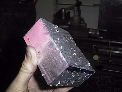 |
From chop-sawed block of aluminum to squared cube in 20 minutes. This became the mounting base for the drive motor; alignment was very important. Some builders poo-poo the need for a vertical mill but what they will never have are really square parts to build with. And when you work with gears, this makes all the difference in the world. |
 |
 |
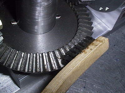
The weapon motor installed in the pod. The hose clamps permitted easy replacement as well as tooth alignment by slight adjustments of the motor in and out. In the end those clamps ripped apart and we lost a motor - so don't EVER use them to fasten something heavy. Some heavy grease brushed into the 12 pitch teeth helped everything start to wear in a bit. |
 |
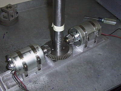 |
Here is the entire module without the top bearning or side plates in place yet. At this point, I was thinking that this design was really coming together well. | |
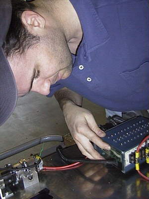 |
Tony installs a thin Lexan cover over our Vantec 36E to keep out all the arena floor crud and metal chips from work. We also installed a few strips of double-sided sticky tape on the inside bottom of the robot - sort of a "machinists flypaper" - they were covered with plastic and metal chips by the end of the event! | |
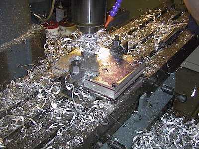 |
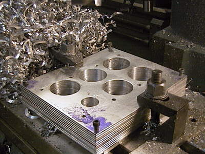
This robot was a NiCad monster. So we needed a good way to hold the 200+ cells that powered the weapon and drive. Tony came up with this idea of "battery cards" made from aluminum that would each hold three six-cell packs on either side. So I band sawed them up, stacked them with double-stick tape and clamped them to the mill for lightening and drilling. |
 |
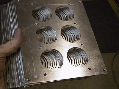 |
The center circles were both lightening holes and air vents. Two cards were separated by vertical stand-offs to form a "battery tower," holding 72 cells. Two towers powered the weapon motors and one tower ran the drive system. It was part of a redundant system approach that ended up saving our bacon in the melee. | |